Product Information
In order to meet the increasingly special and specific sheet metal forming requirements resulting from the need for complex and multi-profile geometries, Special Springs presents a new generation of cylinders with controlled return.
Due to the specifics of these parts, the size of the cylinders has to be determined according to the info received through the Questionaire which will needed to be filled in for us to quote a price. Please download the linked questionnaire, fill in as accurately as possible and return it to us using our contact us form. From there we will get in contact shortly with a quote for you.


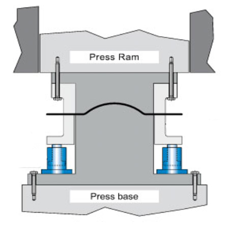
The positioning of the cylinders inside the tool is free and depends solely on the projects requirements; the command unit must be placed near by the press, in an open area so as not to be in the way or create a nuisance.
The use of hydraulic fluid enables an easy and optimal regulation of heat dispersal thanks to the heat exchanger which switches on automatically whenever the need arises.
This guarantees maximum reliability and operational constancy, allowing for working speeds of up to 25 cycles per minute.
Although the intrinsic compressability of the hydraulic fluid at the end of the compression phase results in a slight subsidence of rod retention, the extent of the latter is guaranteed to reach at most 0.2 mm.
![]()
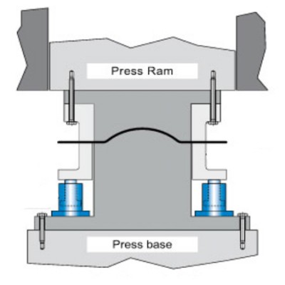
The air contained within the system must always be drained.This operation must take place during the installation and loading procedure of the hydraulic fluid, hence it is necessary for the cylinders to be accessible.
Once this operation has been performed, it is possible to disconnect the quick coupling connectors from the command unit and to proceed with the tool assembly.
AC 3100

| Model | Stroke Cu mm | L mm | L min mm | F max (daN) a 250 bar | F min (daN) a 30 bar | L cm3 | Vcons cm3 |
|---|---|---|---|---|---|---|---|
| AC 3100 - 25 - A | 25 | 126 | 101 | 3140 | 380 | 12,57 | 31,4 |
| AC 3100 - 50 - A | 50 | 176 | 126 | 3140 | 380 | 12,57 | 62,8 |
| AC 3100 - 80 - A | 80 | 236 | 156 | 3140 | 380 | 12,57 | 100,5 |
| AC 3100 - 100 - A | 100 | 276 | 176 | 3140 | 380 | 12,57 | 125 |
| AC 3100 - 125 - A | 125 | 326 | 201 | 3140 | 380 | 12,57 | 157 |
AC 5700

| Model | Stroke Cu mm | L mm | L min mm | F max (daN) a 250 bar | F min (daN) a 30 bar | L cm3 | Vcons cm3 |
|---|---|---|---|---|---|---|---|
| AC 5700 - 25 - A | 25 | 126 | 101 | 5725 | 690 | 22,9 | 57 |
| AC 5700 - 50 - A | 50 | 176 | 126 | 5725 | 690 | 22,9 | 114,5 |
| AC 5700 - 80 - A | 80 | 236 | 156 | 5725 | 690 | 22,9 | 183 |
| AC 5700 - 100 - A | 100 | 276 | 176 | 5725 | 690 | 22,9 | 229 |
| AC 5700 - 125 - A | 125 | 326 | 201 | 5725 | 690 | 22,9 | 286 |
AC 7800

| Model | Stroke Cu mm | L mm | L min mm | F max (daN) a 250 bar | F min (daN) a 30 bar | L cm3 | Vcons cm3 |
|---|---|---|---|---|---|---|---|
| AC 7800 - 25 - A | 25 | 126 | 101 | 7790 | 935 | 31,17 | 78 |
| AC 7800 - 50 - A | 50 | 176 | 126 | 7790 | 935 | 31,17 | 156 |
| AC 7800 - 80 - A | 80 | 236 | 156 | 7790 | 935 | 31,17 | 249 |
| AC 7800 - 100 - A | 100 | 276 | 176 | 7790 | 935 | 31,17 | 249 |
| AC 7800 - 125 - A | 125 | 326 | 201 | 7790 | 935 | 31,17 | 39 |