
Our unique and patented safety features are designed to protect in key areas - over pressure. over stroke, uncontrolled speed & contaminants. All of these represent a danger to personnel and will irreparably damage the cylinder. Our safety features therefore primarily protect against injury but are also cost saving - and all at no extra cost!
SKUDO - Active Protection Against Contaminants
OPAS - Over Pressure Active Safety
OSAS - Over Stroke Active Safety
USAS - Uncontrolled Speed Active Safety
SKUDO is a cap made from plastic material, fixed to the end of the rod end following its movement and represents the utmost active protection of the cylinder against liquid and solid stamping contaminants. SKUDO is an international patented device.
SKUDO is a protection device not subject to wear, that has no contact with moving parts and guarantees total protection of the rod and seal. It eliminates the risk of filling the internal chamber of the cylinders with stamping liquids preventing an uncontrolled increase of the pressure with possible structural collapse.
SKUDO is the most advanced protection against liquid and solid stamping contaminants available.
Case History:
In addition to SKUDO protection, we offer a complete range of secondary wipers, SW, to improve performances of gas springs used in heavy contamined environments. The new secondary wipers, made in polyurethane, are designed for a perfect fitting with many series of gas springs. Secondary wipers can be ordered separately from the gas springs.
This is a device installed directly on the bottom of the cylinder with the function of exhausting the gas pressure when it exceeds the default maximum value. OPAS activates itself by breaking the safety valve then releasing the pressure inside the cylinder completely.
OPAS is installed in the following series or parts of them: M, ML, KE, RV, RF, RS. The models fitted with it are clearly indicated on the PDF information.
This is a device designed to exhaust the pressure inside the cylinder when the real working stroke exceeds the maximum nominal value of the stroke. It consists of a groove machined on the inner wall of the cylinder that creates a discontinuity at the contact surface of the outer sealing element of the bushing and allows the gas to vent in the occasion of an overstroke.
OSAS is activated by pushing the bushing downwards which brings the outer seal element on the discontinuity of the wall thus exhausting the pressure inside the cylinder. OSAS is self activated so is activated before the pressing pad collapses against the cylinder body, preventing any structural damage to the cylinder and improving the users safety.
OSAS is installed in the following series or parts of them: M, ML, KE, RV, RF, RS. The models fitted with it are clearly indicated on the PDF information.
USAS is an unique safety solution device, which exhausts pressure in a controlled and complete way, without ejection of parts when the cylinder has been stressed by uncontrolled return of the piston rod. This is typically caused by the seizure or jam of the die plates or stamped parts that, subjected to pressure thrust, are released in an uncontrolled manner. USAS usually does not activate after the first impact/shock, but only after a certain number of non controlled impacts.
USAS is activated by the upward shift of the bushing that takes the outer sealing element of the bushing onto the discontinuity on the inner wall of the cylinder. It is activated as a result of the abnormal mechanical load generated by the non controlled return of the piston rod, deforming the contact section of the C-ring, thus allowing the upward shift of the same bush.
USAS self activates without causing structural damages to the cylinder, further improving safety for users.
The models fitted with it are clearly indicated on the PDF information.
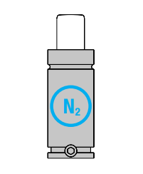 |
Charge only with Nitrogen Gas |
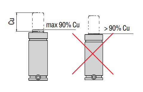 |
All Special Springs nitrogen cylinders are designed with a stroke reserve from 1 to 3 mm (except M90/ TBM-TBI-TEM). Therefore, the nominal value (Cu) is fully applicable. However, it is recommended not to exceed 90% of Cu in practical use in order to avoid risk of any extra stroke caused by changes or errors in tools. This would result in irreparable damages to the cylinders and serious danger to personnel. |
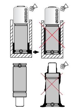 |
In presence of liquid or solid contaminants, use cylinders with SKUDO. In absence of cylindrs with SKUDO protection, a significant improvement could be obtained by mounting the cylinders in upside-down position. |
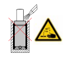 |
Avoid contact with contaminant (soda or chlorites) on the cylinders. If used for cleaning tools, we recommend you to carefully remove any remainng liquid from the cylinders. |
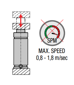 |
Do not confuse the maximum speed with the recommended maximum number cycles/min, as indicated in each family of the product. |
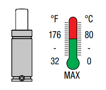 |
Operating Temperature |
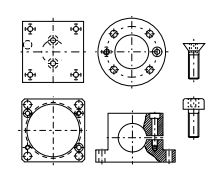 |
Always fix the gas springs directly through the threaded holes on the bottom or with the fixing elements provided |
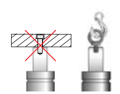 |
Use the threaded hole on the rod only for handling. |
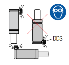 |
Wn discharging using a DDS device, direct the gas flow away form operator.he |
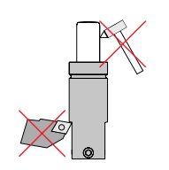 |
Avoid any mechanical tooling or impact on the body and the rod. |
 |
If a cylinder has structural damage, fully exhause all pressure before any form of handling. |
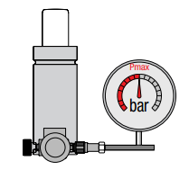 |
When charging do NOT exceed the maximum recommended pressure for each model. |
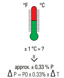 |
Any variation in temperature, respect to the nominal calculation value of 20°C, causes a change in gas pressure (P). |
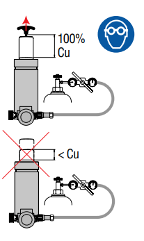 |
Ensure that the rod is 100% extracted when charging. For cylindres without a threaded hole on the rod, initially charge to 5 bar (75 psi) to extract the rod completely, then charge to the required. |
 |
Before disposing of gas spring ensure that all residual pressure is fully exhausted. |
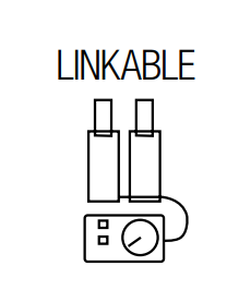 |
All gas springs which can be connected to the system and are specifically coded are supplied without the one-way valve, without pressure and with only the closure plug of the connection hole (excluding M90, M200, RV170, RV320). If you wish to convert independent gas springs into system-connectable gas springs, order the necessary hoses and connections, and follow the specific instructions for every series published on site www.specialsprings.com. |
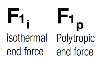 |
Both the isothermal and polytropic end forces are indicated in the catalog for all models. The isothermal end force at 100% Cu is a value calculated in static conditions. For user information, the approximated values of polytropic force indicated is calculated at thermal regime, 100% Cu, ca 30 SPM costant press speed and room temperaturet at around 20°C. For further details please contact us. |
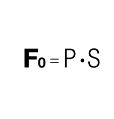 |
To calculate the initial force (Fo) of each gas spring, multiply the maximum charging pressure (P) to the area of sealing (S), rod or piston, of the gasket seal. |
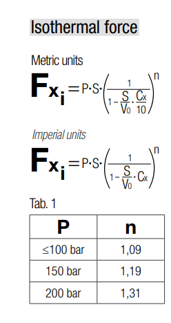 |
To calculate the intermediate isothermal force (Fx i) to a specific working stroke (Cx), use the formula by replacing the relative numeric values. The exponent (n) varies in function of the charging pressure (P) as indicated. For intermediate pressure values, it is possible to calculate the (n) value proportionally. |
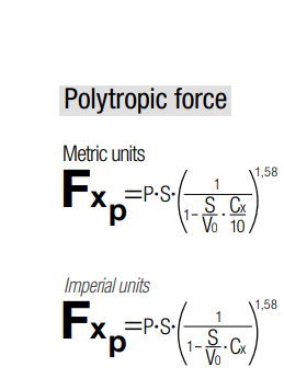 |
To calculate the approximated value of polytropic intermediate force (Fx p) to a specific working stroke (Cx), use the formula by replacing the relative numeric values. The exponent (n) for the polytropic force shall be assumed to be equal to 1,58 for the majority of normal applications. |
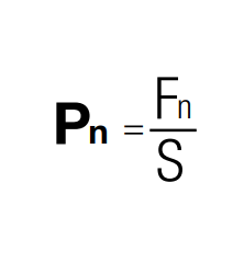 |
To determine the pressure level required to achieve a force (Fn) different from the nominal one (Fo), divide the required force (Fn) by the area of sealing, rod or piston, of the gasket seal. |
 |
Do not exceed the maximum rod speed indicated. Exceeding speeds can reduce the gas spring's life. |
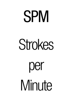 |
The maximum frequency range of use recommended to 100 % Cu is indicated for every model. The lower value is referred to the longest stroke, the higher value refers to the shortest stroke. Higher frequencies can reduce the gas spring duration. |
 |
ALL Special Springs gas springs fulfill the requirements of the European directive concerning pressure equipment (2014/68/EU), applied in the European Union from 19th July 2016. This directive sets out the standards for pressure equipment and defines them as vessels, piping and In particular, according to the directive 2014/68/EU, pressure equipments are classified by category and they shall bear the CE marking with the identification number of the manufacturer when the result of pressure P(bar) X fluid volume Vo(dm³) is 50 or more. The CE marking is mandatory for Categories II and III, but discretionary for Category I. All gas springs which result of P x Vo is less than 50 are subject to Article 4.3 of the same directive and they do not bear the CE marking. |
 |
SPECIAL SPRINGS guarantees that the gas springs manufactured and sold by SPECIAL SPRINGS are free from manufacturing defects. This Warranty is valid for the period of (2) two years from the date of purchase, or for 200,000 linear meters of stroke*, or for 2,000,000 strokes, whichever occurs first. (*100,000 linear meters for the HT Series) The Warranty is applicable only to gas springs installed, used, and repaired according to SPECIAL SPRINGS guidelines. In case of alleged defect, all useful information - including the date of purchase and the working conditions of gas springs - shall be notified to Berger Tools. Before using SPECIAL SPRINGS gas springs, always refer to the information on the safety and the compliance with regulations as indicated in the Instruction Sheet, the technical documentation and/or on the website www.specialsprings.com. By “WARRANTY” it is meant the repair or free replacement of the product, which is recognized by SPECIAL SPRINGS as defective in manufacture or materials. SPECIAL SPRINGS is not liable for any damage caused by negligence, misuse and noncom- pliance with the warning and indications contained in SPECIAL SPRINGS guidelines. Furthermore, heavy working conditions or external causes may reduce the lifetime of gas springs significantly. Warranty legal terms on www.specialsprings.com |
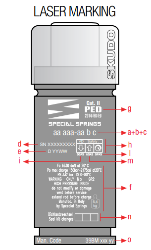 |
a) Model code |
 |
If pressure losses occur after extended use or particularly heavy applications, this indicates that the sealing gaskets are worn or damaged. Using special tools and kits, and with the support of videos and detailed instructions, it is possible to restore the original seal and guide conditions. Maintenance must only be conducted by qualified personnel. Errors would cause serious injury or reduce the working life of the gas springs. Before carrying out any work on the system,fully exhaust all pressure and ensure that the rod is fully retracted into the body. As prescribed by the guidelines of PED 2014/68/EU, the company taking care of the maintenance for gas springs laser |