Rubber & Urelast spring design information including springs and sheets outlining tolerances, and how to calculate stroke rate and space requirements.
Elastomer springs can be used in single, parallel or row arrangement. Their force-distance behaviour corresponds to the familiar laws governing spring behaviour. For optimum application of elastomer springs, the following installation information must be complied with:
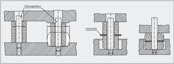
Guidance and centering of the springs is ideally achieved with guide bolts (DIN ISO 10069-1). They are required for unfavourable spring geometry and in order to avoid buckling of the spring stacks.
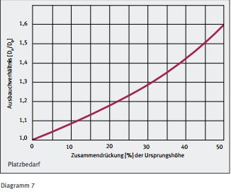
EFFBE elastomer materials are incompressible. Consequently, for installation dimensions, clearences, such as distances for the bulging out of the springs must be taken into account. The crucial factor is the spring stroke; simplified, the bulging percentage equals the compression percentage. A safety margin must also be provided (See Diagram 7).
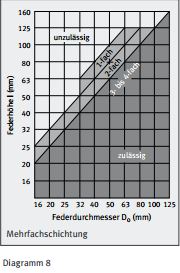
For greater spring strokes, elastomer springs are stacked in rows; in this regard the geometry must be complied with (See Diagram 8). The Individual springs must be seperated from each other by spring washers. AAt equal spring forces, the individual spring strokes are added together. The spring stacks must always be guided.
The contact faces of the spring should be Rz 25 to RZ 40 in accordance with DIN ISO 10069-1. They can be flat, elevated or in a recess. When mounted at a raised level, the diameter must at least be equal the dimention of the spring collar. If mounted in a recess, the clearence must be adapted to the bulge factor (See Diagram 7).
For dynamic continuous use, the stroke rate in conjunction with the deformation must always be considered. If the limit values are underranged the service life increases due to lower self-warming (See Diagram 6).
Dimensional tolerances in accordance with DIN ISO 3302-1 M3 apply at a reference temperature of +200C.
Hardness tolerences in accordance with DIN ISO 10069-1 apply with the tolerance of ±3 Shore A.
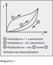
Prior to the final dynamic stress, the springs should be loaded and unloaded several times (up to 10 times, Diagram 5). All subsequent diagrams present the 10th load change of quasistatic deformation. They correspond to DIN ISO 10069-1.
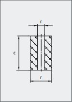
Permissible dimensional deviations in accordance with DIN ISO 3302-1 M3:
|
Nominal Dimension Range mm |
Permissible Dimensional Deviation F±MM |
Permissible Dimensional Deviation C±MM |
|---|---|---|
| Up To 6,3 | 0,25 | 0,4 |
| Greater than 6,3 to 10 | 0,3 | 0,5 |
| Greater than 10 to 16 | 0,4 | 0,6 |
| Greater than 16 to 25 | 0,5 | 0,8 |
| Greater than 25 to 40 | 0,6 | 1,0 |
| Greater than 40 to 63 | 0,8 | 1,3 |
| Greater than 63 to 100 | 1,0 | 1,6 |
| Greater than 100 to 160 | 1,3 | 2,0 |
| Greater than 160 | 0,8% | 1,3% |
F= Fixed Dimension
C= Closure Dimension
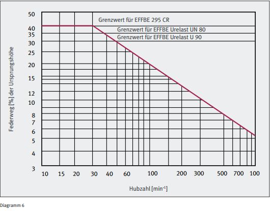
The values of the table apply as maximum spring stroke based on the original height (L) of the spring, dependant on the stroke rate.
| EFFBE elastomer springs |
EFFBE 295 Chloroprene rubber CR70 |
EFFBE Urelast Polyurethane rubber UN80 |
EFFBE Urelast Polyurethane rubber U90 |
|---|---|---|---|
| Spring deflection (S) max. | 40% | 35% | 30% |
| Bottoming tendency (Ss) from original height | 3-5% | 5-7% | 5-8% |
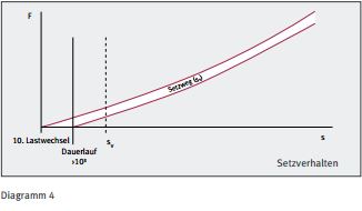
In addition to the type of deformation, its size and the temperature, the spring material determines the settling distance. The information is based on values recorded in practice that are reached in dynamic application after 103 load changes at 90% (See Diagram 4).
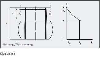
The intial drop in force can be compensated through and increase in the force specification by FV. At high dynamic stress the practical increase values for quality are:
The preload deflection must be selected greater than the settling distance (See Diagram 3) due to the bottoming tendency and to ensure positive-locking spring application.
