Our use of Cookies on this Website

We use cookies to to give you the best experience possible & analyse our traffic. By clicking “Accept Cookies”, you agree to the storing of cookies on your device to enhance site navigation, analyse site usage, and assist in our marketing efforts.

We also share information about your use of our site with our social media, advertising, and analytics partners who may combine it with other information that you’ve provided to them or that they’ve collected from your use of their services.

Please view our cookie policy or privacy policy for more information.

Manage Cookies Accept Cookies

Vishnu's Value Vault - April's Clearance Parts - Now Available - Click Here

BERGER TOOLS LTD

PDFs


Catalogue Technical Specification
ISO Fundamental Tolerances
Keyway and Key Details DIN6885
Cross Holes GN110
Further Description for Position Indicators GN000.8
Further Description for Position Indicators GN000.3
Installation_sequence_GN323.8.pdf

CAD Data


3D CAD Files
2D CAD Files
GN323.8 with Bore Type R 3D CAD Model
GN323.8 with Keyway Type R 3D CAD Model
GN323.8 with Bore Type A 3D CAD Model
GN323.8 with Keyway Type A 3D CAD Model

Close
Close

GN323.8 Aluminium Disc Handwheel For Position Indicators

CloseNextPrevious


CloseNextPrevious

GN323.8: Disc Handwheel
Type: A - without Handle


CloseNextPrevious

GN323.8: Disc Handwheel
Type: R - with Revolving Handle


CAD Viewer Technical Data

Choose your Part

Please select desired options to reveal part number, price and availability

Options

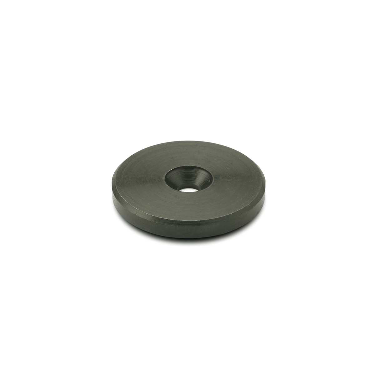
Bore Code B - Without keyway.

Bore Code K - With keyway.

Type A - Without handle.

Type R - With revolving handle GN798

CAD Viewer Technical Data

Product Description

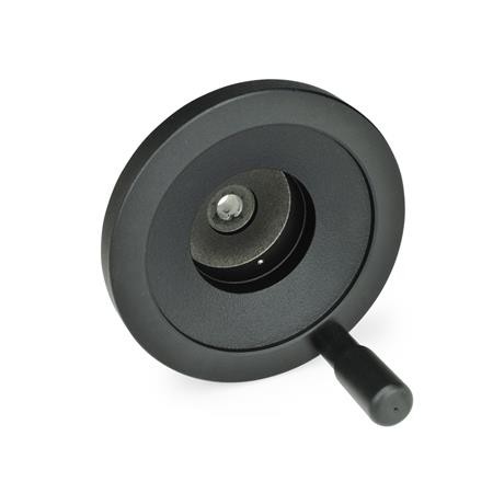
GN323.8 Aluminium Disc Handwheel for Position Indicators.

These GN 323.8 handwheels have a cleverly designed recessed hub to house position indicators GN000.8. They can be supplied with or without a revolving handle and are comfortable in use.

The hub dimensions (for fitting) correspond to those of disc handwheels GN323 and handwheels according to DIN950.

Installation Instructions

1. Install the handwheel to the spindle and fix it with the grub screw or keyway/countersunk washer.

2. Turn the spindle to the starting point (0 position).

3. Move the position indicator manually to the 0 position before mounting it.

4. Install the position indicator into the recess of the hub and fix it with the screw. Do not apply unnecessarily excessive torque to avoid deformation of the housing!

5. Rotate the handwheel and ascertain that the starting point of the spindle is aligned with the 0 position of the two pointers (GN 000.8) respectively pointer. Should that not be the case, the screw has to be loosened and the position indicator adjusted. Tighten the screw again.

Specification


Related Series


Your Berger Sign Up Trade Accounts Discounts & Delivery Charges Catalogues Exhibitions Contact Us FAQs
Our Reviews & Feedback Company Business Code of Practise Terms and Conditions Quality & Certification Products Subscribe to our newsletter
Shopping with Us Your Berger Sign Up Trade Accounts Discounts & Delivery Charges Catalogues Exhibitions
About Us Company Business Code of Practise Terms and Conditions Quality & Certification
Customer Services Contact Us FAQs Our Reviews & Feedback
Latest Product Information & Special Offers Subscribe to our newsletter

© Berger Tools Ltd 2018 Admin Website by Goldhosts
Key Cloud...
GN323.8 Disc Handwheel Disc Handwheel Aluminium Disc Handwheel Disc Handwheel for Position Indicator